
It's the middle of February, freezing rain, sleet, and snow. It is 3:00 in the morning, the coraplast and PVC pipe called to me. I slowly descend into my basements skunk works. It is time to build a fairing. I have decided to makes small changes from the original design. I plan to use the same mounting system as for the first fairing. Anyone who knows me will understand the fact, I am not making a monochrome fairing, this time it will be tricolor. The colors this time yellow, orange, and green colors of the Outspokin' Wheelmen. They have not gotten new jerseys yet so I'm building my own.
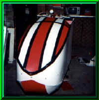
The problem with my first fairing, it is to blunt in the front. When I bent the lower pieces I made the curve to abrupt. So the front of the fairing is rather flat as this picture shows.
 click
on image for larger picture
For the new fairing I decided to make a smaller radius curve at the front of the nosecone. Another design change was make the front of the piece that wraps around deeper. The problem with my first nosecone was it was to blunt. When I bent the lower pieces the curve was too sharp and made an almost straight up and down front on the nosecone. I reasoned it deflected the air less to move it to the side instead of down. Now most of the air is displaced to the sides. I decided the old fairing was to low in the rear and did not come up to my shoulders.
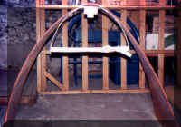
The one of the reasons the first fairing is so blunt along front end was the fact if the supporting aluminum strap must be flat when it attaches to the PVC tee. For the new fairing the coraplast could be separated from the aluminum support strip in the front. I drew its shape of the curve for the front on a piece of poster board.
 click
on image for larger picture
I then attached the PVC tee to the support strip in the middle. I then curve the sides of the strip to match the drawn curve on the poster board. Since the middle of the strip was attached to the PVC tee it had to remain straight. Therefore I move it down from the middle of the curve until the sides were able to bent to match the curve.
With the main piece for the nosecone I first drew it as it was originally set up for the first fairing. I then lowered the bottom edge by 6 in. in the front. I redrew the curves on the sides to accommodate this design change.
I then cut out the piece using a pair of scissors. I prefer scissors because they're easier to control than a utility knife. Now for the low-tech way of getting the coraplast the bent nicely in the center. I held the piece up by the middle next to a hundred watt light bulb. I moved around a little bit ended bent quite nicely.
I then made my next departure from fairing construction according to Ed Gin. I did not mount the front support strip to the bike before adding the coraplast piece. I drew a line along the fairing piece to indicate where the strip should be attached. I then drilled through the coraplast and the aluminum strip. Then I connected them with a pop rivet. I then proceeded to attach the support strip with four pop rivets on each side.
 click
on image for larger picture
I then attached the resulting piece to the front of the bike. Here I learnt the reason for attaching the support strip to the bike before attaching the coraplast. The piece was at the wrong angle and was tilting down instead of being what I considered level.
 click
on image for larger picture
At first I thought I would have to drill out three pop rivets on each side adjust the fairing peace to the position I wanted it to drill holes in the coraplast and apply new pop rivets.
However, another idea came to mind. Since the front of the support strip is not attached to the coraplast I just gave the support boom a pull in the direction I wanted it. It worked perfectly. I then constructed the top of the nosecone similar to Ed Gin's method except I used smaller strips so they can make a nicer curve.
The support piece for the lower section of the nosecone has little curve. Since there is very little change I just bent the straight piece at the correct length with to a leg is to attach to the main coraplast piece. I the unused five pieces of coraplast to attach to the bottom of the fairing and it support piece. This seemed to work just fine.
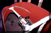
For the side mounting brackets I did not use slotted U channel for shelves. Instead I used aluminum U channel for capping half-inch plywood. It was lighter and didn't have the slots pre cut. My drill bit always hung up on the slots.
 click
on image for larger picture
I attached the brackets with three pop rivets. I then took a piece of green coraplast and formed a solid arch for the panel's of the upper nosecone to end on. Just in keeping with the color scheme.
click on image for larger picture
I constructed the back of the fairing by taking a a sheet of yellow coraplast. I cut it to the desired width. I then formed it into a U using a hair dryer to help the process along. I left it bent in this U shape overnight.
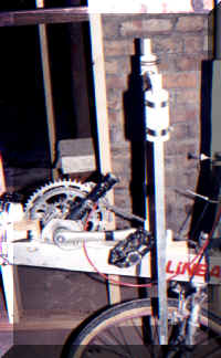
When I started the next day I position the coraplast so it matched the lower edge of the nose, I taped the lower edges with duct tape. I made sure the coraplast was touching the rear rack and leveled the piece up I then taped the upper edges to help hold it in place. Next with a length of PVCs pipe that had a tee on each end was secured with hose clamps to the front of the rear rack. This was the support for the back half of the fairing. I then drilled holes through the coraplast and into the tee. I connected the two with pop rivets using a support washer to help it with grip.
I then shaped the upper edge of the rear fairing using a utility knife. I made a trunk using the same techniques as for the first fairing. And it was ready to go after taping the joints.
I found that the new fairing was approximately 2 mi. an hour faster than the first fairing. After riding it for two weeks I decided my design was too susceptible to crosswinds. I decided to cut the side area of the fairing.
Starting at the edge of the rack I drew a gentle incline to the middle of the nosecone's lower edge. Then using a utility knife I cut along the line.
I then sealed the bottom edge of the rear fairing using some leftover coraplast. This is to keep the back half of the fairing from cupping air. I connected the two sides using a piece of coraplast under the seat Velcroing each side to it. This seemed to work very well. If you have any questions about the fairing construction please first refer to the construction of the first fairing and look at Ed's seminar on fairing construction.